This article contains my technical opinions and is for general information purposes only. The topic covers power and control cable bending radii which can differ from data / fiber / mining cable requirements.
Introduction to Bending Radius
This newsletter will discuss minimum bending radius requirements for power and control cables in Canada. Confusion arises from a mix of code rules, tables, and manufacturer’s specification sheets, which may conflict. The intent of the CE Code is to prevent cable damage by over-bending, but its generic nature requires installers to look deeper into the topic.
Cable bending radius limitations are mainly affected by conductor size, insulation thickness, number of conductors, and shielding / armour type. Most stated bend radius values are for statically installed cables which become even more critical when the cables are installed under tension. Industry standards like IEEE 1185 provide general cable information, CE Code rules provide code requirements, and manufacturer spec sheets provide cable-specific requirements. All should be considered in your project.
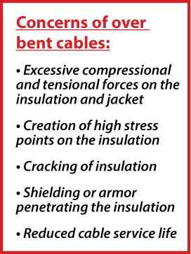
Understanding cable bend radii can help jobsite installations. Over-bending cables may damage the jacket, armour, and/or insulation, reducing cable life. Using too large a bend radius can result in higher cable tray costs.
CE Rules for Bend Radii
Below are some of the main CE Code bend radii rules for power and control cables.
12-110 Radii of Bends in insulated conductors and cables – “The radii of bends in insulated conductors and cables shall be sufficiently large to ensure that no damage is done to the conductors or cables or to their insulation, covering, or sheathing.” This is a general rule that applies to all conductor / cable types. Additional code rules provide further requirements for specific cable types.
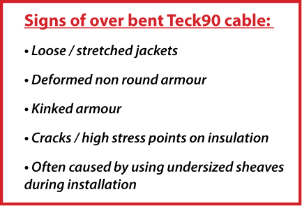
12-614 Radii of bends in armoured cables – Requires 6 x Cable OD minimum bend radius for low voltage armoured cables and that the bends should not distort the armour. Sub-rule 3 lays out requirements for armoured cables pulled in conduit.
12-712 Addresses bend radii for MI (mineral insulated), aluminum sheathed, and copper sheathed cables – Requires 9 x cable OD for Corrugated aluminum or copper sheathed cables. Examples are Vitalink 2-hour fire-rated cables (copper sheathed) and corrugated armour VFD cables (aluminum sheathed).
36-102 Radii of Bends for High Voltage cables – Points you to Table 15.
IEEE Standard 1185 Tables 12 – This standard is commonly referred to in manufacturer installation guides.

IEEE Standard 1185 Bend Radius Table
Table 12 - Comparative Minimum Bend Radius Factors

Practical Applications
In general, Canadians use 6 x cable OD for low voltage Teck90 cable minimum bend radius (as measured at the innermost surface) to line up with CE Code 12-614 (1), or 7 x cable OD to line up with what is stated on most manufacturer’s specification sheets. Note NEC 330.24 states 7 x cable OD for UL MC cable (this is the US code requirement for their equivalent cable).
Shielded 5KV and higher voltage cables show an example of a conflict between CE Code requirements and industry standards. CE Code Table 15 applies to these cables but is unclear and appears to be based upon single conductor cables, resulting in high values for multi-conductor cables.
Table 15 calls for 12 X cable OD but it is unclear if it refers to the overall cable OD or the individual conductor OD in a multi-conductor cable. Both the NEC (National Electrical Code) and C68.10 (CSA cable standard these cables are built to) allow for 7 x cable OD min bend radius of multi-conductor cables and 12 X OD for single conductor cables. Cable spec sheets frequently state 7 x cable OD minimum bend radius for this cable type. Using a 12 X cable overall OD bend radius for 3 conductor cables may require larger cable trays than the project has space for. Some manufacturers will supply a letter stating that their cables are suitable for installation at 7 x cable OD, which can be used as support for clarification with your project’s authority having jurisdiction.
Interestingly, the CE Code does not differentiate between static and dynamic (ie. During installation) bend radii. However, 12-110 requires the radii of bend to be sufficient to prevent damage to the conductors or cable. Cable pull calculations will often show that larger bend radii are required to not exceed the cable’s side wall bearing pressure limitations during installation.
Understanding cable bend radius requirements can help maximize cable lifespans while minimizing jobsite costs. Refer to the CE Code for code requirements, manufacturer specification sheets for specific product requirements, and IEEE 1185 Tables 1 & 2 for general industry practice.
For more information on cable installation and sizing, read our articles on medium voltage cable sizing CE code ampacity table D17, cable pulling calculations, and how to handle low temperature cables.


